- How to activate multisim as a student how to#
- How to activate multisim as a student code#
- How to activate multisim as a student windows#
After simulating a design, you can stream data to Measurements Live and compare the simulation with real-time measurements using the NI ELVIS III Oscilloscope To use the Multimeter click o Creating a design and Simulating a design contain a tutorial that introduces you to Multisim Live and its many functions using the circuit shown below (RC filter). 1) Multimeter Use the Multimeter to measure AC or DC voltage or current, and resistance or decibel loss between two nodes in a circuit. Some of the basic instruments needed for this lab are described below. In addition to input pins, the decoder has a enable pin Multisim offers multiple ways to analyze the circuit using virtual instruments. A decoder circuit takes binary data of 'n' inputs into '2^n' unique output. A decoder circuit takes multiple inputs and gives multiple outputs.
How to activate multisim as a student code#
Open Multisim and create a design Multisim is opened from the Start Menu: Start Menu > All Programs > National Instruments > Circuit Design Suite 11.0 > Multisim 11.0 (Version numbers may differĪ decoder is a combinational logic circuit that is used to change the code into a set of signals.

How to activate multisim as a student windows#
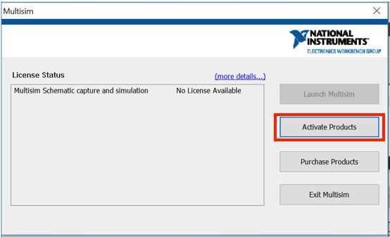
e the results, copying and pasting Multisim windows into lab reports and other documents as needed. 4-to-16 decoder/demultiplexer truth table Multisim 14.2 Help This 4-line-to-16-line decoder uses TTL circuitry to decode four binary-coded inputs into one of sixteen mutually exclusive outputs when both the strobe inputs are low. We are going to activate Multisim through the most convenient option There are three ways to activate Multisim from this window. Select Activate to start the activation process. Regardless of which edition you installed, a dialog will pop up giving you four options: Evaluate, Activate, Purchase, and Exit. 7-Segment Display indicator (BCD DECODER) - Multisim Live. Then building a digital circuit and simulating it, adding pin. How to activate multisim as a student how to#
A quick tutorial on how to use Multisim V14.1 starting with a simple switch, resistor and LED. G1 is an active high ENABLE or multiplexed inverting data input nG0 is an active low ENABLE or multiplexed noninverting data input. Configure this window as shown in the following figure. Select Tools✼omponent Wizard from the Multisim main menu. Step 1: Enter Initial Component Information. In the next steps, you will learn to use the Component Wizard to create the THS7001 in Multisim. For the counter in this tutorial we will be using: CLK - 50MHz clock on the boar 3 to 8 Logic circuit Decoder Simulation using Multisim Select the connectors that you will be using on the PLC. thanks in Advance Select the Digilent board you will be using from the drop down menu. this is what i did Are there decoder chips available at Multisim? If yes, where can I get them from? I want a 3-8 decoder 74LS138. When the inputs are 000 then the first output of 8 output must be glow and when the inputs are 001 then the second output of 8 output must be glow and so on until the last output. To be more explanatory what i want is using only and or may be nand gate and build a decoder itself. Decimal/ Function Copy of 3-to-8 Decoder. The decoder accepts 4-bit binary-coded-decimal (BCD) and, depending on the state of the auxiliary inputs, decodes this data to drive a 7-segment display indicator. 


74LS47N is a BCD to 7-Segment active-low decoder with open-collector outputs to drive indicator segments directly. Academic & Research Enjoy the videos and music you love, upload original content, and share it all with friends, family, and the world on YouTubeħ4LS47N Decoder. Decoders - Multisim Help - National Instruments. IN THIS VIDEO I HAVE EXPLAINED THE FUNCTIONING OF DECODER CIRCUIT AND AFTER THAT I. decoder is a very important combinational circuit in digital electronics. Decoder A decoder is a circuit that has n inputs and 2n outputs and outputs 1 on the wire corresponding to the binary number represented by the inputs.S.


 0 kommentar(er)
